Have you ever wondered what happens the moment you press the power button on your computer? Behind that brief pause, before your screen lights up, a complex series of processes is taking place. This article will dive into the fascinating world of firmware, exploring how different components interact during the boot process.
By understanding these connections, you will get a clearer picture of foundational elements that bring your system to life. Our primary focus will be on the Intel x86 architecture, but many principles apply across other architectures as well.
If you missed the first part of our series, click here to catch up. Now, let's uncover the mysteries behind the firmware.
Table of Contents:
- Definitions
- Overall Firmware Architecture
- First-Stage Boot Loader (FSBL)
- BIOS (POST phase)
- UEFI Platform Initialization (PI)
- coreboot
- Other solutions
- Second-Stage Boot Loader (SSBL)
- BIOS
- UEFI
- OS Boot Loader
Definitions
- Firmware: a specialized type of software embedded in hardware, providing low-level control and enabling the hardware to function correctly and interact with other system components.
- Basic Input/Output System (BIOS): a legacy firmware (originally created for the IBM PC) responsible for hardware initialization after platform power-on. Nowadays, it's often vaguely referred to as the complete set of firmware.
- Bootloader: a general name for firmware that is responsible for booting a computer. It is used as a modern concept in place of BIOS, often providing a framework with bootstrap code to initialize the processor and chipset, as well as interfaces for third parties (for example, motherboard developers) to perform platform-specific initialization.
- Payload: A software to be executed when the bootloader exits. Could be a second-stage bootloader, Operating System, BIOS/UEFI application, etc. It usually takes care of bootstrapping flow according to firmware design.
- The usage of the terms BIOS and bootloader can be confusing, as their meanings depend on the context. However, when someone mentions firmware, BIOS, or bootloader, they are generally referring to the complete set of firmware running between the operating system and the hardware.
- EFI vs. UEFI: The Extensible Firmware Interface (EFI) was the original specification developed by Intel. The Unified Extensible Firmware Interface (UEFI) is the successor to EFI, created by the UEFI Forum to standardize and extend the original specification. In most cases, EFI and UEFI are used interchangeably.
Overall Firmware Architecture
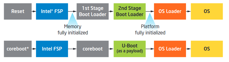
To understand how the firmware components interact, we will explore the entire architecture with all its connected parts. The execution flow, shown in the diagram below, starts from the reset vector, which is part of the First-Stage Bootloader. From there, it progresses through various firmware stages:
Firmware or BIOS can generally be divided into two main parts, with a typically minimal interface between them:
- Hardware Initialization: Responsible for initializing the hardware components of the system.
- Interface to the OS and User: Provides the necessary interfaces to the operating system and the user.
The design of the platform firmware can be either monolithic, combining hardware initialization and boot functionality, or it can follow a modular and staged boot flow. The choice of design depends on the system requirements and may be preferable for certain devices.
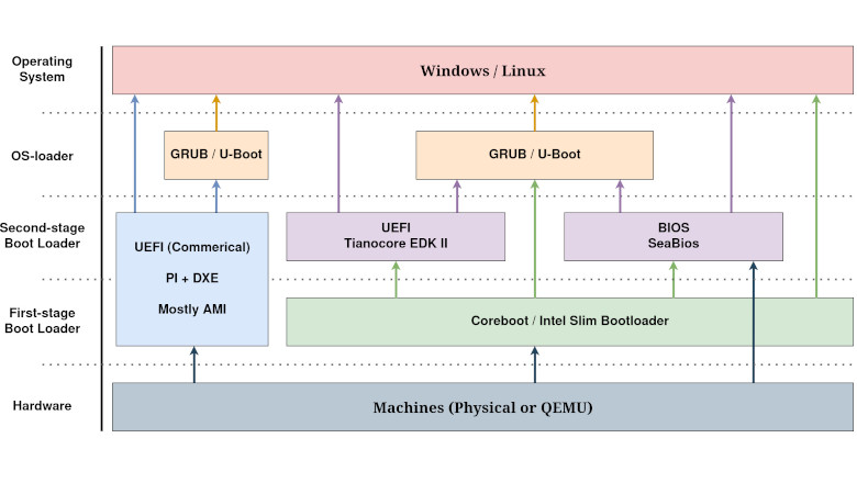
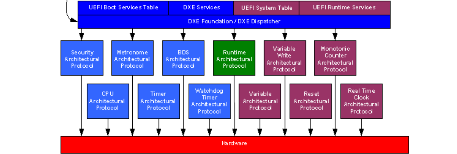
The following diagram illustrates how different firmware components interact and can be used together to support the boot process (arrows indicate the sequence of execution):
If these diagrams seem complex now, don't worry. Review them again after reading this article, and they will be clearer.
First-Stage Boot Loader (FSBL)
This piece of firmware is designed to initialize computers and embedded systems with a focus on minimal hardware initialization: to do only what is absolutely needed, then pass control to Second-Stage Bootloader in order to boot the operating system. The FSBL doesn't load operating systems from storage media other than the flash chip. Since it only initializes the underlying hardware and doesn't handle boot media like hard drives, SSDs, or USB flash drives, another piece of software is required to actually boot an operating system.
Key Responsibilities of FSBL:
- CPU: Switching from 16-bit Real Mode to 32-bit Protected Mode (note: or in Virtual 8086 mode in case of BIOS).
- Cache Utilization: Calling FSP-T to configure Cache-As-RAM for the C environment.
- Debug Port: Initializing the configured debug port by calling board-specific initialization methods.
- Memory Initialization: Invoking FSP-M to initialize the system’s main memory and saving crucial system memory information.
- GPIO: Configuring General-Purpose Input/Output (GPIO) pins for interfacing with external devices.
- Silicon: Performing early platform initialization and using FSP-S to complete chipset, CPU, and IO controller initialization.
- PCI Enumeration: Enumerating PCI devices and allocating resources such as memory addresses and IRQs.
- Payload Preparation: Setting up SMBIOS and ACPI tables, including the preparation information (coreboot tables, HOBs) required to be passed to the payload.
- Loading and Handoff: Loading and transferring control to the payload.
BIOS (POST Phase)
In the early days of computing, open-source software was not widely popular, and most BIOS implementations were proprietary. There are only a few available open solutions providing BIOS POST source code, such as Super PC/Turbo XT BIOS and GLaBIOS. These projects were designed to work on IBM 5150/5155/5160 systems and most XT clones.
However, the more well-known open-source BIOS implementations, like OpenBIOS and SeaBIOS, do not perform hardware initialization because they are not intended to run on bare hardware. But they are widely used as Second-Stage Bootloaders and run natively in virtual environments like QEMU and Bochs.
In any case, there's little chance that you will need to work directly with these early BIOSes or delve deeply into their specifics. But if you're interested in exploring, the mentioned repositories are a good starting point.
As far as current development trends go, there appears to be no ongoing development of proprietary BIOS solutions, and such projects have become obsolete in the face of modern alternatives.
UEFI Platform Initialization (PI)
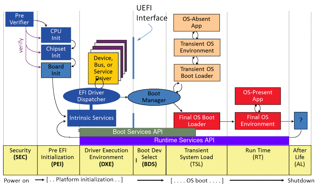
The boot process follows a staged flow, starting from the left and moving to the right in the next figure. The timeline of the platform boot process is divided into the following phrases as indicated by yellow boxes:
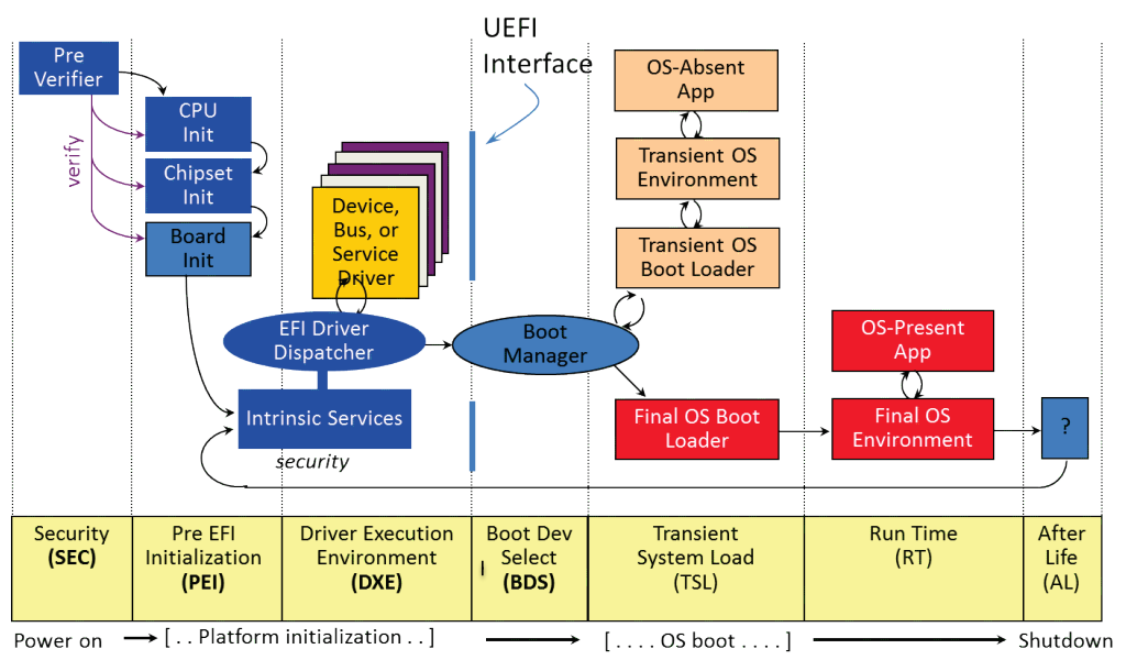
- Security (SEC): The first phase after a reset vector, its primary function is to set up Temporary RAM (CPU Cache-As-RAM or SRAM).
- Pre-EFI Initialization (PEI): This phase dispatches specialized drivers called Pre-EFI Initialization Modules (PEIMs). These modules handle essential hardware initialization, such as configuring the CPU and chipset and setting up main memory (DRAM).
- Driver Execution Environment (DXE): In this phase, the rest of the system initialization is performed. The DXE phase provides UEFI services and supports various protocols and drivers necessary for the system's operation.
- Boot Device Select (BDS): This phase implements the platform boot policy, determining the boot sequence and selecting the appropriate boot device/loader.
- Transient System Load (TSL): During this phase, the system runs applications using UEFI services to prepare the OS. It includes the transition from the UEFI environment to the operating system, concluding with the
ExitBootServices()call. - Run Time (RT): In this phase, the operating system is fully operational, managing the system under its control.
- After Life (AL): This phase deals with scenarios where the hardware or OS crashes/shuts down/reboots. The firmware may attempt recovery actions, however, UEFI PI Specification doesn't define specific requirements or behaviors for this phase.
This process and its execution phases are covered by the UEFI Platform Initialization (PI) Specification. However, there is also the UEFI Interface (indicated by the bold blue line in the picture), which is not part of the previous document and is described in the UEFI Specification. Although the names and frequent use of UEFI can be confusing, these two documents have different focuses:
- UEFI PI Spec: Focuses on interfaces between low-level firmware components and details how these modules interact to initialize the platform.
- UEFI Spec: Defines the interfaces for interaction between the Operating System (OS) and the firmware. This will be discussed further in the context of Second-Stage Bootloader. Note that the UEFI Specification relies on the PI Specification.
Essentially, both specifications are about interfaces, but at different levels. For detailed information, you can access both specifications on the UEFI Forum website.
UEFI PI was initially designed as a unified firmware solution, not considering the distinction between first-stage and second-stage bootloaders. However, when we refer to UEFI as a First-Stage Bootloader, it includes the SEC, PEI, and early DXE phases. The reason we divide DXE into early and late stages is due to their different roles in the initialization process.
In the early DXE phase, drivers typically perform essential CPU/PCH/board initialization and also produce DXE Architectural Protocols (APs), which help isolate the DXE phase from the platform-specific hardware. APs encapsulate the details specific to the platform, allowing the late DXE phase to operate independently of the hardware specifics.
Coreboot
Detailed articles on how Coreboot works are coming soon. Follow my social media – they will be published very soon!
Other solutions
- Intel Slim Bootloader (SBL): pure first-stage bootloader that provides only the core hardware components initialization, followed by loading the payload. However, it works only on Intel x86 platforms and does not support AMD x86 or other architectures.
- Das U-Boot: both a first-stage and second-stage bootloader. However, support for booting directly from the x86 reset vector of the platform (known as bare mode) is limited compared to other firmware. It is more popular on embedded systems and ARM-based devices. As a second-stage bootloader, U-Boot implements a subset of the UEFI but focuses on embedded systems.
Second-Stage Boot Loader (SSBL)
After the initial hardware setup is completed, the second stage comes into play. Its primary role is to set up a software interface between the operating system and platform firmware, ensuring that the OS can manage system resources and interact with hardware components.
The SSBL aims to hide hardware variations as much as possible, simplifying OS and application development by handling most of the hardware-level interfaces. This abstraction allows developers to focus on higher-level functionalities without worrying about the underlying hardware differences.
Key Responsibilities of SSBL:
-
Platform Information Retrieval: Obtains platform-specific information from the First-Stage Bootloader, including memory mapping, SMBIOS, ACPI tables, SPI flash, etc.
-
Run Platform Independent Drivers: Includes drivers for SMM, SPI, PCI, SCSI/ATA/IDE/DISK, USB, ACPI, network interfaces, and so on.
-
Services Implementation (aka Interface): Provides a set of services that facilitate communication between the operating system and hardware components.
-
Setup Menu: Offers a setup menu for system configuration, allowing users to adjust settings related to boot order, hardware preferences, and other system parameters.
-
Boot Logic: Mechanism to locate and load the payload (probably operating system) from available boot media.
BIOS
The interface in the BIOS is known as BIOS services/functions/interrupt calls. These functions provide a set of routines for hardware access, but the specific details of how they are executed on the particular hardware of the system are hidden from the user.
In 16-bit Real Mode, they can be easily accessed by invoking a software interrupt via INT x86 assembly language instruction. In 32-bit Protected mode, almost all BIOS services are unavailable because of the different way segment values are handled.
Let's take for example Disk Services (INT 13h), which provides sector-based hard disk and floppy disk read and write services using Cylinder-Head-Sector (CHS) addressing, as an example of how this interface can be used. Let's say we want to read 2 sectors (1024 bytes) and load them at memory address 0x9020, then the following code could be executed:
mov $0x02, %ah       # Set BIOS read sector routine
mov $0x00, %ch       # Select cylinder 0
mov $0x00, %dh       # Select head 0 [has a base of 0]
mov $0x02, %cl       # Select sector 2 (next after the
                     # boot sector) [has a base of 1]
mov $0x02, %al       # Read 2 sectors
mov $0x00, %bx       # Set BX general register to 0
mov %bx, %es         # Set ES segment register to 0
mov $0x9020, %bx     # Load sectors to ES:BX (0:0x9020)
int $0x13            # Start reading from drive
jmp $0x9020          # Jump to loaded code
If you're interested in how this service is written in SeaBios, have a look at src/disk.c.
BOOT phase
-
Starts searching for a bootable device (it can be a hard drive, CD-ROM, floppy disk, etc.) by reading the first 512-byte sector (sector zero) from the devices.
-
The bootstrap sequence in the BIOS loads the first valid Master Boot Record (MBR) that it finds into the computer's physical memory at the physical address 0x7C00 (hint: 0x0000:0x7c00 and 0x7c0:0x0000 refer to the same physical address).
-
BIOS transfers control to the first 512 bytes of the payload. This loaded sector, which is too small to contain the entire payload code, serves the purpose of loading the rest of the payload from the bootable device. At this point, the payload can use the interface exposed by the BIOS.
It's noteworthy that BIOS specifications didn't exist in the early days. BIOS is a de facto standard - it works the way it worked on actual IBM PCs, in the 1980s. The rest of the manufacturers just reverse-engineered and made IBM-compatible BIOSes. As a result, there was no regulation to prevent BIOS manufacturers from inventing new BIOS functions or having overlapping functionalities.
Unified Extensible Firmware Interface (UEFI)
As mentioned before, UEFI itself is just a specification and has many implementations. The most widely used one is TianoCore EDK II, an open-source reference implementation of the UEFI and PI specifications. While EDKII alone is not enough to create a fully functional boot firmware, it provides a solid foundation for most commercial solutions.
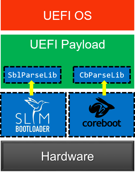
To support different First-Stage Bootloaders and provide a UEFI interface, the UEFI Payload project is used. It relies on the initial setup done and platform information provided by boot firmware to prepare the system for the UEFI environment.
The UEFI Payload uses the DXE and BDS phases, which are designed to be platform-independent. It offers a generic payload that can adapt to different platforms. In most cases, it doesn’t require any customization or platform-specific adjustments and can be used as-is by consuming platform information from the First-Stage Bootloader.
Variants of UEFI Payload:
-
Legacy UEFI Payload: Requires a parse library to extract necessary implementation-specific platform information. If the bootloader updates its API, the payload must also be updated as well.
-
Universal UEFI Payload: Follows the Universal Scalable Firmware (USF) Specification, using Executable and Linkable Format (ELF) or Flat Image Tree (FIT) as a common image format. Instead of parsing them itself, it expects to receive the Hand Off Blocks (HOBs) at the payload entry.
While the Legacy UEFI Payload works fine, the EDK2 community is trying to shift the industry towards the Universal UEFI Payload. The choice between payloads depends on your firmware components. For example, it's not possible to run the Legacy Payload with SMM support on Slim Bootloader without my patch. On the other hand, using the Universal Payload with coreboot requires a shim layer to translate coreboot tables into HOBs, a feature only available in the StarLabs EDK2 fork.
Interface
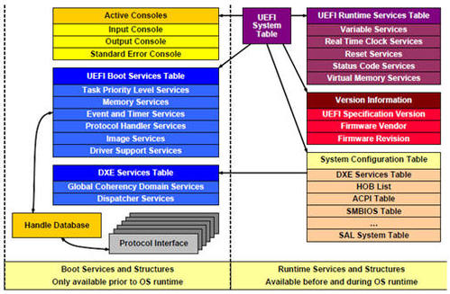
Every UEFI-compliant system provides a System Table that is passed to every code running in the UEFI environment (drivers, applications, OS loaders). This data structure allows a UEFI executable to access system configuration tables such as ACPI, SMBIOS, and a collection of UEFI services.
The table structure is described in MdePkg/Include/Uefi/UefiSpec.h:
typedef struct {
  EFI_TABLE_HEADER                   Hdr;
  CHAR16                             *FirmwareVendor;
  UINT32                             FirmwareRevision;
  EFI_HANDLE                         ConsoleInHandle;
  EFI_SIMPLE_TEXT_INPUT_PROTOCOL     *ConIn;
  EFI_HANDLE                         ConsoleOutHandle;
  EFI_SIMPLE_TEXT_OUTPUT_PROTOCOL    *ConOut;
  EFI_HANDLE                         StandardErrorHandle;
  EFI_SIMPLE_TEXT_OUTPUT_PROTOCOL    *StdErr;

  //
  // A pointer to the EFI Runtime Services Table.
  //
  EFI_RUNTIME_SERVICES               *RuntimeServices;

  //
  // A pointer to the EFI Boot Services Table.
  //
  EFI_BOOT_SERVICES                  *BootServices;

  UINTN                              NumberOfTableEntries;
  EFI_CONFIGURATION_TABLE            *ConfigurationTable;
} EFI_SYSTEM_TABLE;
Services include the following types: Boot Services, Runtime Services, and Services provided by protocols.
UEFI abstracts access to the device by setting up UEFI Protocols. These protocols are data structures containing function pointers and are identified by a Globally Unique IDentifier (GUID) that allows other modules to locate and use them. They can be discovered through Boot Services.
A UEFI driver produces these protocols, and the actual functions (not pointers!) are contained within the driver itself. This mechanism allows different components within the UEFI environment to communicate with each other and ensures that the OS can interact with devices before loading its own drivers.
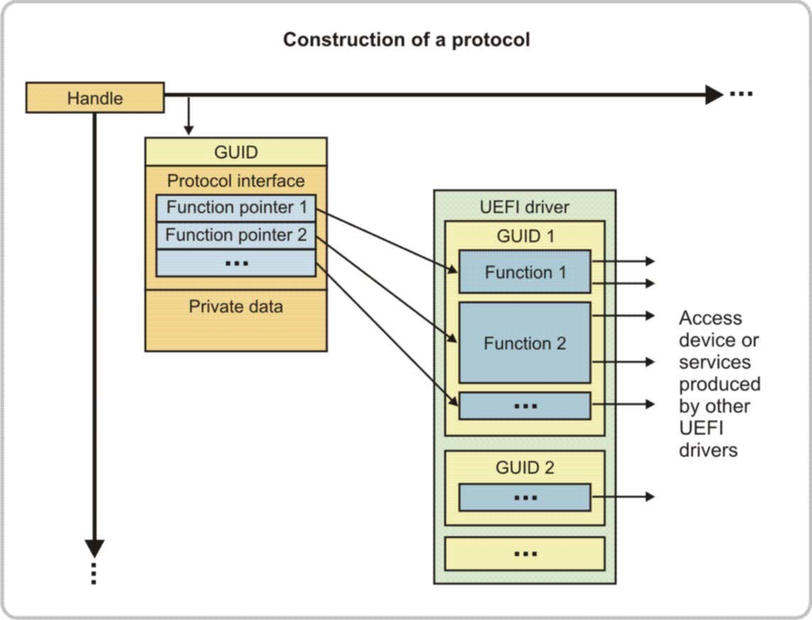
While some protocols are predefined and described in the UEFI specification, firmware vendors can also create their own custom protocols to extend the functionality of a platform.
Boot Services
Provide functions that can be used only during boot time. These services remain available until the EFI_BOOT_SERVICES.ExitBootServices() function is called (MdeModulePkg/Core/Dxe/DxeMain/DxeMain.c).
Pointers to all boot services are stored in the Boot Services Table (MdePkg/Include/Uefi/UefiSpec.h):
typedef struct {
  EFI_TABLE_HEADER        Hdr;
  ...
  EFI_GET_MEMORY_MAP      GetMemoryMap;
  EFI_ALLOCATE_POOL       AllocatePool;
  EFI_FREE_POOL           FreePool;
  ...
  EFI_HANDLE_PROTOCOL     HandleProtocol;
  ...
  EFI_EXIT_BOOT_SERVICES  ExitBootServices;
  ...
} EFI_BOOT_SERVICES;
Runtime Services
A minimal set of services are still accessible while the Operating System is running. Unlike Boot Services, these services are still valid after any payload (for example, OS bootloader) has taken control of the platform via a call to EFI_BOOT_SERVICES.ExitBootServices().
Pointers to all runtime services are stored in Runtime Services Table (MdePkg/Include/Uefi/UefiSpec.h):
typedef struct {
  EFI_TABLE_HEADER                  Hdr;
  ...
  EFI_GET_TIME                      GetTime;
  EFI_SET_TIME                      SetTime;
  ...
  EFI_GET_VARIABLE                  GetVariable;
  EFI_GET_NEXT_VARIABLE_NAME        GetNextVariableName;
  EFI_SET_VARIABLE                  SetVariable;
  ...
  EFI_GET_NEXT_HIGH_MONO_COUNT      GetNextHighMonotonicCount;
  EFI_RESET_SYSTEM                  ResetSystem;
  ...
} EFI_RUNTIME_SERVICES;
The picture below shows the timeline for boot and runtime services, so you can see exactly when each one is active.
Boot Device Select (BDS) Phase
The UEFI spec defines a boot policy engine called the UEFI boot manager. It will attempt to load UEFI applications in a specific order. This order and other settings can be configured by modifying global NVRAM (nonvolatile random-access memory) Variables. Let's discuss the most important of them:
Boot####(####is replaced by a unique hex value) — a boot/load option.BootCurrent— the boot option used to start the currently running system.BootNext— the boot option for the next boot only. This replacesBootOrderfor one boot only and is deleted by the boot manager after first use. This allows you to change the next boot behavior without changingBootOrder.BootOrder— the ordered boot option load list. The boot manager tries to boot the first active option in this list. If unsuccessful, it tries the next option, and so on.BootOptionSupport— the types of boot options supported by the boot manager.Timeout— the firmware's boot managers timeout, in seconds, before automatically choosing the startup value fromBootNextorBootOrder.
These variables can be easily obtained from Linux by using efibootmgr(8):
[root@localhost ~]# efibootmgr
BootCurrent: 0000
Timeout: 5 seconds
BootOrder: 0000,0001,2001,2002,2003
Boot0000* ARCHLINUX HD(5,GPT,d03ca3cf-1511-d94e-8400-c7a125866442,0x40164000,0x100000)/File(\EFI\ARCHLINUX\grubx64.efi)
Boot0001* Windows Boot Manager  HD(1,GPT,6f185443-09fc-4f15-afdf-01c523565e52,0x800,0x32000)/File(\EFI\Microsoft\Boot\bootmgfw.efi)57a94e544f5753000100000088900100780000004200430044039f0a42004a004500430054003d007b00390064006500610038003600320063002d1139006300640064002d0034006500370030102d0061006300630031002d006600330032006200330034003400640034003700390035007d00000033000300000710000000040000007fff0400
Boot0002* ARCHLINUX HD(5,GPT,d03ca3cf-1511-d94e-8400-c7a125866442,0x40164000,0x100000)
Boot2001* EFI USB Device    RC
Boot2002* EFI DVD/CDROM RC
Boot2003* EFI Network   RC
Let's take a look at the booting by relying on the code snippet above. UEFI will start iterating the BootOrder list. For each entry in the list, it looks for a corresponding Boot#### variable — Boot0000 for 0000, Boot2003 for 2003, and so on. If the variable does not exist, it continues to the next entry. If the variable exists, it reads the contents of the variable. Each boot option variable contains an EFI_LOAD_OPTION descriptor that is a byte-packed buffer of variable length fields (it's just the data structure).
The data structure is described in [MdePkg/Include/Uefi/UefiSpec.h][ https://github.com/tianocore/edk2/blob/edk2-stable202405/MdePkg/Include/Uefi/UefiSpec.h#L2122)
typedef struct _EFI_LOAD_OPTION {
  /// The attributes for this load option entry.
  UINT32                         Attributes;

  /// Length in bytes of the FilePathList.
  UINT16                         FilePathListLength;

  /// The user readable description for the load option.
  /// Example: 'ARCHLINUX' / 'Windows Boot Manager' / `EFI USB Device`
  // CHAR16                      Description[];

  /// A packed array of UEFI device paths.
  /// Example: 'HD(5,GPT,d03ca3cf-1511-d94e-8400-c7a125866442,0x40164000,0x100000)/File(\EFI\ARCHLINUX\grubx64.efi)'
  // EFI_DEVICE_PATH_PROTOCOL    FilePathList[];

  /// The remaining bytes in the load option descriptor are a binary data buffer that is passed to the loaded image.
  /// Example: '57a9...0400' in Boot0001 variable
  // UINT8                       OptionalData[];
} EFI_LOAD_OPTION;
At this point, the firmware will examine a Device Path (EFI_DEVICE_PATH_PROTOCOL). In most cases, our computer is booted up from a storage device (Hard Drive/SSD/NVMe/etc). So, the Device path would contain HD(Partition Number, Type, Signature, Start sector, Size in sectors) node.
- Type — indicates the format used for the partitioning scheme with the keywords MBR (1) or GPT (2).
- Signature — a 4-byte MBR signature if the Type is MBR, or a 16-byte UUID if the Type is GPT.
Note: If you're interested in how to translate other paths, read UEFI Specification v2.10, 10.6.1.6 Text Device Node Reference.
UEFI will look into the disk and see if it has a partition matching the node. If it exists, it should be labeled with a specific Globally Unique IDentifier (GUID) that marks it as the EFI System Partition (ESP). This one is formatted with a file system whose specification is based on the specific version of the FAT file system and is named EFI File System; actually, it's just a regular FAT12/16/32.
- Native boot: if the Device Path contains an explicit path to the file
File(\Path\To\The\File.efi), then UEFI will look for that specific file. For example, theBoot0000option containsFile(\EFI\ARCHLINUX\grubx64.efi). - Fallback boot: if the Device Path simply points to a disk, then in such situations, the firmware will use a fallback boot path that is based on architecture —
\EFI\BOOT\BOOT{arch}.EFI(BOOTx64.EFIfor amd64 orBOOTia32.EFIfor i386/IA32). This mechanism allows the bootable removable media (for example, a USB drive) to work in UEFI; they just use a fallback boot path. For example, theBoot0002option will use this mechanism.
Note: All Boot#### options mentioned above refer to the boot options displayed in the example output of efibootmgr.
In both cases, the UEFI Boot Manager will load the UEFI Application (it might be OS bootloader, UEFI Shell, utility software, System setup, and whatever) into memory. At this moment, control is then transferred to the UEFI application’s entry point. Unlike BIOS, the UEFI application can return control to the firmware (besides the situation, when the application takes over control of the system). If it happens or anything goes wrong, the Boot Manager moves on to the next Boot#### entry, and follow exactly the same process.
The specification mentions that the boot manager can automatically maintain the database variables. This includes removing load option variables that are not referenced or cannot be parsed. Additionally, it can rewrite any ordered list to remove any load options without corresponding load option variables.
The above text describes the UEFI booting. Also, UEFI firmware can run in Compatibility Support Module (CSM) mode that emulates a BIOS.
OS Boot Loader
A piece of software started by the firmware (usually Second-Stage Bootloader) and using its interface to load the OS kernel. It can be as complex as an OS, offering features such as:
- Reading from various filesystems (HFS+, ext4, XFS, etc)
- Interacting over a network (e.g., TFTP, HTTP)
- Booting Multiboot-compatible kernels
- Chainloading
- Loading initial ramdisks (initrd)
- And more!
The common designs of these programs are beyond the scope of this article. For a detailed comparison of popular OS bootloaders, you can refer to the ArchLinux wiki and the Wikipedia article.
Windows system uses its proprietary OS bootloader known as the Windows Boot Manager (BOOTMGR).
Firmware is no longer a small, complex piece of code. It has become a huge amount of complex code, and current trends only contribute to this. We can run Doom, Twitter, and many other interesting applications on it.
Understanding the overall architecture helps to organize these components in your mind. By examining the design of existing firmware, you gain insight into the fascinating process that unfolds each time a computer is powered on. This top-down perspective not only clarifies the role of each part but also highlights the sophisticated and evolving nature of modern firmware systems.
Resources
- UEFI Specification Version 2.10
- UEFI Platform Initialization Specification Version 1.8 (Errata A)
- EDK II Documentation
- Slim Bootloader Project Documentation
- UEFI boot: how does that actually work, then?
- Understanding modern UEFI-based platform boot
- Anatomy of the UEFI Boot Sequence on the Intel Galileo
- Very simple note on disk device "paths" in some common architectures.
- How Computers Boot Up
[story continues]
tags