The raw data captured by image sensors are, in essence, just cold digital signals. To transform these data into the vivid photos we see on screens, they must undergo a complex process—the Image Signal Processor (ISP). The ISP acts like a digital "darkroom," completing dozens of algorithmic processes in a very short time. This article will take readers into this black box to explore the magical journey from raw sensor data to beautiful images.
In-depth Analysis of Key ISP Steps
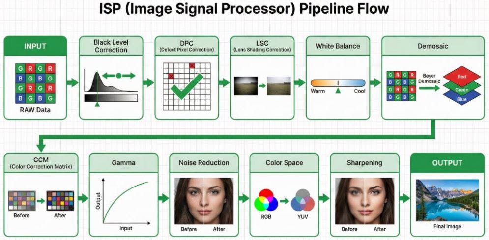
A typical ISP processing pipeline is a highly sequential process, where the output of each stage serves as the input for the next. The diagram below illustrates the complete flow from raw sensor data to the final image output, followed by an in-depth analysis of each step.
1. INPUT (RAW Data)
The starting point of image processing is the raw data captured by the sensor. As shown in the Bayer array block in the diagram, this data is typically arranged in a Bayer pattern, where red, green, and blue filters are interleaved. Therefore, each pixel at this stage only records single-color information.
2. Black Level Correction
As indicated by the histogram shift in the diagram, this step aims to correct the baseline offset generated by the sensor under completely dark conditions, ensuring that the "black" in the image truly becomes zero, thereby enhancing contrast. The underlying principle is that photosensitive components, due to physical factors like dark current, output non-zero voltage values even in the absence of light. Without correction, dark areas of the image would appear murky, and the accuracy of subsequent color calculations would be affected.
- Implementation: The edges of the sensor typically feature "optical black pixels," which are physically shielded from light. The ISP reads the average value of these pixels as a reference offset and subtracts this value from all pixel values across the entire image.
- Engineering Challenges: Black level varies with temperature and gain, necessitating dynamic compensation mechanisms.
- Tuning and Trade-offs: The main parameter is Offset. If the offset is too high, dark details will be clipped, resulting in "crushed blacks"; if too low, dark areas will appear grayish, leading to a decrease in overall contrast.
3. DPC (Defect Pixel Correction)
As shown by the checked squares replacing red crosses in the diagram, this step's task is to identify and repair defective pixels on the sensor (such as permanently bright pixels or non-responsive dark pixels) caused by manufacturing defects or aging. These defects stem from unavoidable physical imperfections during the production of photosensitive components.
- Implementation: Divided into "static correction" (scanning and recording defect pixel coordinates at the factory) and "dynamic correction" (detecting pixels with significant differences from their neighbors through algorithms).
- Engineering Challenges: Requires precise differentiation between "true high-frequency details" and "defective pixels" to avoid mistakenly blurring the image.
- Tuning and Trade-offs: The key parameter is Threshold. A threshold that is too low will mistakenly identify high-frequency details (such as text, textures) in the image as defective pixels, causing blurring; a threshold that is too high will fail to effectively detect and repair true defective pixels.
4. LSC (Lens Shading Correction)
As illustrated by the before-and-after comparison of the landscape photo, this step aims to compensate for the brightness attenuation (vignetting) and potential color shifts at the image edges caused by the optical characteristics of the lens, ensuring a more uniform brightness and color distribution across the entire frame. Lens Shading arises from a combination of factors, primarily including:
Cos⁴ Falloff: This is an inherent physical property of optical systems, referring to the natural attenuation of light intensity from the center to the edge of the lens, proportional to the fourth power of the cosine of the incident angle.
Mechanical Vignetting: Caused by physical obstruction of light at the edges by internal lens structures (such as aperture blades, lens barrel).
CRA Mismatch (Chief Ray Angle Mismatch): Microlenses on the sensor are designed to receive light at specific angles. When the chief ray angle (CRA) of the light exiting the lens does not match the optimal reception angle of the microlenses, it leads to reduced light-gathering efficiency of edge pixels.
These factors collectively lead to brightness and color attenuation at the image edges, and the goal of LSC is to precisely compensate for these effects.
- Implementation: The ISP pre-stores a correction gain map. There are two main implementation methods: 1. Radius-based: Assumes vignetting is radially symmetrical around the optical center, where the gain value is a function of the pixel's distance from the center. 2. Grid-based: Divides the image into a grid, stores gain values for each grid vertex, and then interpolates to calculate the precise compensation value for each pixel. The latter can correct more complex, asymmetrical shading.
- Engineering Challenges: Color shifts vary under different light sources, requiring multiple sets of parameters to switch between.
- Tuning and Trade-offs: The core parameter is Gain Strength. If the strength is too low, vignetting cannot be fully compensated, and the image remains uneven; if too high, it will over-enhance edge brightness and simultaneously amplify noise in that area, leading to diminishing returns.
5. White Balance
The color temperature bar adjustment in the diagram intuitively demonstrates the core function of white balance: adjusting the proportions of red, green, and blue primaries in the image according to the color temperature of the scene's light source, ensuring that white objects appear neutrally white in the image. The principle is that different light sources (such as 2800K tungsten light and 6500K daylight) have different spectral distributions. The purpose of white balance is to ensure that under any light source, white objects in the image satisfy the condition R=G=B.
-
Implementation: Common algorithms include "Gray World Assumption" and "Perfect Reflector." The core is to calculate R gain and B gain (usually based on G) and apply them to the entire image. In recent years, machine learning (ML) techniques, especially Convolutional Neural Networks (CNNs), have also been widely applied to white balance. Through training on large amounts of image data, ML models can more accurately estimate color temperatures in complex or mixed lighting environments and perform scene classification, thereby achieving smarter and more human-perceptual white balance effects.
-
Engineering Challenges: Mixed light sources, lack of white reference objects, and color preferences are the main challenges faced by white balance.
-
Tuning and Trade-offs: The main parameters are R/G Gain and B/G Gain. If R/G Gain is too high, the image will appear reddish and warm; if B/G Gain is too high, the image will appear bluish and cool. Precise matching is required to restore neutral colors in the scene.
Note: For detailed information on white balance, please refer to "Image Engineer's Notes #3: Auto Exposure, White Balance, Auto Focus ‒ Demystifying the Camera's 'Decision Intelligence' 3A Algorithms."
6. Demosaic
As shown in the diagram, this step reconstructs the monochromatic raw data in Bayer format into a full-color RGB image where each pixel contains complete red, green, and blue color information. Since each pixel in Bayer format only contains single-color information, the core of demosaicing is to utilize spatial correlation, referencing surrounding pixels to "guess" the missing color information for each pixel.
- Implementation: Ranging from simple "bilinear interpolation" to complex "edge-directed interpolation" (which first detects local edge directions and interpolates along those directions to preserve edge sharpness and reduce false colors).
- Engineering Challenges: Prone to generating moiré patterns and zipper effects when processing high-frequency stripes.
- Tuning and Trade-offs: The main parameters are Edge Threshold and False Color Suppression. An edge threshold that is too low will mistakenly identify noise as edges, creating erroneous textures; false color suppression that is too high may eliminate normal color details, leading to desaturated colors.
7. CCM (Color Correction Matrix)
The before-and-after comparison of color blocks in the diagram illustrates the role of CCM: converting the color space captured by the sensor into a standard color space (such as sRGB) that is more consistent with human vision, to precisely adjust color saturation and hue. The principle is that the spectral response of the sensor is inconsistent with human eyes (CIE standard observer), and CCM performs correction through linear transformation.
- Implementation: It takes the red, green, and blue primary values read by the sensor and, after a series of weighted calculations, remaps them to the target color space.
- Engineering Challenges: Non-linear response, color cross-contamination, and noise amplification are the main challenges faced by CCM.
- Tuning and Trade-offs: The essence of CCM tuning is to adjust a 3x3 transformation matrix. The diagonal elements in the matrix primarily control the gain of each color channel, affecting the overall saturation and brightness balance of the image; the off-diagonal elements are responsible for cross-compensation between colors, used to correct color casts and adjust hues. Precisely adjusting these matrix coefficients requires balancing the pursuit of vibrant colors, accurate skin tone reproduction, and suppression of noise amplification. For example, excessively increasing saturation may lead to color clipping in highlight areas, while incorrect cross-compensation can cause unnatural shifts in the hue of specific colors (such as red).
8. Gamma Correction
The input-output curve in the diagram vividly explains the process of gamma correction: applying a non-linear curve to adjust the brightness values of an image. The principle is that human perception of brightness is logarithmic (sensitive to changes in dark areas), while sensor output is linear. Gamma correction bridges this gap.
- Implementation: This curve stretches darker areas of the image to make details more apparent, while compressing brighter areas to prevent overexposure, making the final image's light-to-dark transitions and layering more consistent with human visual perception.
- Engineering Challenges: Over-stretching dark areas significantly amplifies noise; at the same time, improper handling of bright details can lead to highlight clipping or color banding, causing high-light areas like skies and lights to lose their sense of depth.
- Tuning and Trade-offs: The main parameter is Curve Shape. A steeper curve slope enhances image contrast but may lose details in bright and dark areas; a gentler slope can enrich layering but may make the image appear flat.
9. Noise Reduction
As illustrated by the before-and-after comparison of the human face image, noise reduction aims to eliminate random noise caused by low light and high ISO, improving image purity. This noise primarily comes from shot noise and read noise.
- Implementation: Noise reduction is mainly divided into spatial noise reduction (2DNR) and temporal noise reduction (3DNR). In practical ISP pipelines, the color format for processing both is not a single fixed answer but depends on product positioning (e.g., mobile phones, webcams, automotive), performance budget, and image quality strategy. However, in most commercial ISP designs, the following common practices are observed:
-
2DNR (Spatial NR) - What Color Format is Typically Used?
Common Position 1: Bayer Domain (Raw Domain)
Processing Format: Raw Bayer (RGrGbB)
Timing: Before Demosaic
Advantages: Can directly model sensor read noise and shot noise; not affected by demosaic interpolation; best SNR
improvement.
Disadvantages: Algorithm design is more complex (needs to consider CFA pattern); commonly found in high-quality ISPs
(e.g., mobile phones, automotive).
Common Position 2: YUV Domain (Luma & Chroma Separate Processing)
Processing Format: YUV (can process Luma Y and Chroma UV separately)
Timing: After Demosaic + CCM
Advantages: Lower computational load; can separate Luma and Chroma noise for targeted processing. Luma Denoise
focuses on preserving details, while Chroma Denoise can use stronger filtering to eliminate large color blotches.
Disadvantages: Noise has already been amplified or mixed by demosaic; excessive Chroma Denoise strength may lead to
color bleeding; commonly found in webcams or low-power ISPs.
-
3DNR (Temporal NR) - What Color Format is Typically Used?
Common Position: Almost exclusively in the YUV Domain
Processing Format: YUV (mostly performs motion detection on Luma Y + temporal filtering)
Timing: After 2DNR
Reasons: Motion detection is most stable on the Luma Y channel; the human eye is most sensitive to brightness changes;
lower memory and computational load.
Why is 3DNR rarely done in the RAW Domain?
Theoretically possible, but practically challenging: RAW data has not undergone color correction, making cross-frame
alignment difficult; motion estimation on a Bayer pattern is complex; high memory bandwidth requirements.
High-end Applications: Some high-end mobile phone ISPs may perform RAW Temporal NR, or consider HDR multi-frame merge as a form of RAW 3DNR.
- Engineering Challenges: The eternal tug-of-war between noise reduction strength and texture retention.
- Tuning and Trade-offs: The main parameters are Strength (noise reduction strength) and Motion Threshold (for 3DNR). Excessive strength makes the image clean but severely loses details like skin texture, creating a "plastic" look. For 3DNR, the Motion Threshold setting is also crucial; too low a value reduces the noise reduction effect, while too high a value can cause ghosting or trailing artifacts on moving objects.
10. Color Space Conversion
The conversion between RGB and YUV color spheres in the diagram illustrates the function of this step: converting an RGB format image to other color spaces, most commonly the YUV format. The purpose is for subsequent compression (like JPEG/H.264) and transmission, by converting the image into a space that separates luminance (Y) and chrominance (U/V). Since the human eye is far more sensitive to luminance than chrominance, in practice, U/V can be downsampled (e.g., to 4:2:0) to save bandwidth without significantly affecting subjective image quality.
-
Tuning and Trade-offs: The main parameter is Chroma Subsampling format. The 4:4:4 format provides the highest color fidelity but has the largest bandwidth and storage requirements; 4:2:2 or 4:2:0 formats save bandwidth by reducing chrominance resolution, with minimal impact on human visual perception, but may produce slight aliasing at color edges in extreme cases.
11. Sharpening
As shown in the before-and-after comparison of the human face image, sharpening aims to enhance the contrast of object edges in the image to compensate for the blurring caused by the optical system and digital processing, making image details appear clearer. A common implementation is "Unsharp Masking," which subtracts a blurred version from the original image to obtain high-frequency components, and then adds these high-frequency components back to the original image.
-
Engineering Challenges: Oversharpening produces white edges (Halo Artifacts).
-
Tuning and Trade-offs: The main parameter is Strength (sharpening strength). If the strength is too low, the image will appear blurry; if too high, it will produce noticeable white edges and amplify noise, making the image look unnatural.
12. OUTPUT (Final Image)
As shown in the final landscape photo, after all the above processing steps, the original RAW data is finally transformed into a high-quality image ready for display, storage, or further application.
Industry Practical Perspectives: Deep Insights from Image Engineers
ISP tuning is never just a simple scientific formula but an art of seeking the optimal solution among physical limitations, algorithmic computing power, and application requirements. From an image engineer's perspective, the requirements for ISP in different industries reflect the differences in their core values:
1. Consumer Electronics: The Ultimate Pursuit of Sensation
In the mobile devices sector, the "appeal" of an image is valued more than its "realism." Engineers invest significant effort in AI scene recognition and beautification algorithms. To achieve a high dynamic range on extremely small sensors, complex Tone Mapping and multi-frame synthesis techniques are core. The challenge here is to complete massive computations within a very short shutter lag and produce "blockbuster" photos that can be directly shared on social media.
2. Video Collaboration: Balancing Skin Tones and Environment
For PC platforms and video peripherals, the core challenge lies in the extreme complexity of indoor lighting (such as the mix of office fluorescent lights and window daylight). The tuning focus for engineers is on "skin tone reproduction" and "white balance stability." Within a limited power budget, it is essential to ensure that people in video conferences look professional and natural. At the same time, 3DNR must provide a clean image in low light without producing distracting motion artifacts.
3. Automotive Imaging: Guardian of Life Safety
In the automotive domain, images are no longer for human viewing but for machines (ADAS/autonomous driving algorithms). The keys here are "extremely high dynamic range (HDR)" and "extremely low latency." Engineers must ensure that when entering and exiting tunnels or facing strong backlighting, the ISP can produce images with clear details in milliseconds, without any artifacts that could cause algorithmic misjudgment. The "beauty" of colors is meaningless here; the "linearity" and "reliability" of the data are the lifelines.
4. Medical and Industrial: The Ultimate Test of Precision
Medical imaging (such as endoscopes) demands the utmost color accuracy, as a slight color cast could affect a doctor's diagnosis of tissue lesions. Industrial vision, on the other hand, pursues absolute geometric accuracy and optical linearity. In these fields, engineers typically disable most "beautification" features, instead focusing on the repeatability and data integrity of the ISP processing.
5. Security and Surveillance: All-Weather Recognition Capability
Challenges in the security sector revolve around "extreme environments." Engineers must extract features sufficient for identifying faces or license plates in extremely low light (even starlight conditions) through powerful noise reduction and gain control. The tuning philosophy here is "visibility" over "beauty," and thermal stability must be guaranteed for 24/7 long-term operation.
6. Drone Industry: The Ultimate Balance of Aerial Perspective
Image engineers in the drone industry face multiple challenges. First is extreme lighting variation; aerial flights often encounter drastic backlighting and ground contrast, requiring the ISP to possess excellent HDR processing capabilities. Second is high-speed motion compensation; how to produce stable images without jello effects through ISP combined with gimbal stabilization and Electronic Image Stabilization (EIS) algorithms during high-speed flight and body vibrations. Third is the low-latency video transmission requirement; for FPV (First Person View) flight safety and real-time control, ISP processing must be extremely efficient to reduce image latency. Finally, under the stringent constraints of lightweight design and power consumption balance, engineers must seek the optimal balance between image quality and computational power within limited battery life and thermal conditions, ensuring image quality without sacrificing flight time and equipment reliability.
Summary
From the raw Bayer data captured by the sensor to a final image rich in color and detail, the journey is a magical one led by the ISP. This article has delved into the twelve key steps of this journey, from basic physical corrections to core color reconstruction, and finally to image quality optimization. We have not only analyzed the technical principles and engineering challenges of each step but also integrated the trade-offs of parameter tuning, revealing the complexity of image tuning. More importantly, through the analysis of practical perspectives from various industries such as consumer electronics, automotive, and medical, we can see that there is no absolute "optimal solution" in ISP tuning. Instead, it is a series of exquisite trade-offs based on the different emphases on "image quality, performance, cost, and reliability" in various application scenarios. Ultimately, the job of an image engineer is to find the perfect balance for the product at the intersection of scientific rigor and artistic sensibility.
Conclusion
An outstanding image engineer must not only master every mathematical model in the ISP Pipeline but also deeply understand the "user needs" behind the product. In the digital darkroom, what we adjust is not just pixels and gains, but the different ways various industries interpret the real world. Understanding these underlying logics is key to tuning the perfect image at the crossroads of technology and art.
Disclaimer
All images in this article are for the sole purpose of illustrating ISP technical concepts and do not represent any specific brand or product. Some images are AI-generated. The content of this article is based on the author's years of practical experience in image engineering and is intended for general technical discussion and experience sharing only. It does not constitute any professional advice or guidance. Readers should evaluate its applicability themselves and are responsible for any actions taken based on the content of this article.