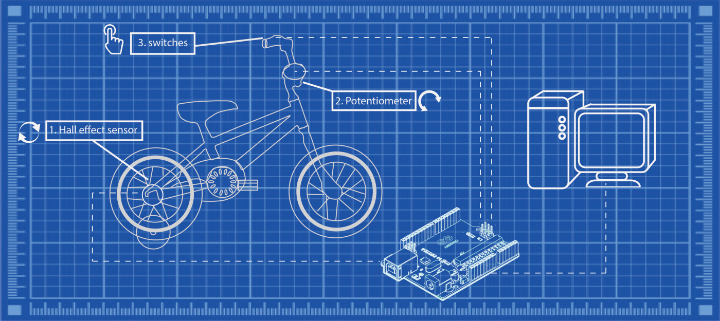
In this short tutorial, I’ll walk you through the process of turning any bicycle into an arcade-like controller for computer games.
your very own keyboard bike.
Foundations:
the rear wheel to spin freely without touching the ground, and allow
the handlebars to turn freely as well. If your kid is propelled forward,
you should NOT proceed to the following steps.
floor beneath the wheel and many more. I personally used the training
wheels to support the rear, but this is your place to get creative, and
more importantly, be responsible. I am deliberately avoiding getting into too much detail about my implementation of this part (you can get a pretty good idea from the various pictures and gifs in this article…) as it is your responsibility to make sure that the bicycle are secure and safe to use.
The plan
sensors to capture the rotation of the rear wheel, position of the
handle bars and some buttons for extra control (these can be easily
programmed later to map any keyboard key). Data from all sensors will be captured and transformed by an Arduino that will function as a keyboard and send keystrokes to a computer running a (most likely racing) game.
Hardware
1. A1302 Hall Effect Sensor — This sensor changes its output voltage when in the proximity of a magnetic field. We will use it to transform the rotation of the rear wheel to a forward key press.
2. 10K ohm linear potentiometer — Used to transform the handlebar orientation to left/right keys.
3. Microswitch — used as extra controllers. I highly recommend using this type of switches (limit switch) and not going for some fancy buttons. these switches are very responsive, whereas some buttons can sometimes be challenging for a kid to press.
Connecting the parts
Hall effect sensor
spaced (that is ~180 degrees apart).
the gif, the sensor itself is located at its end) as close to the wheel
as possible I mounted it to a flexible wire (I used some heavy duty
electrical wire but any wire that will flex and keep its position will
do).
Potentiometer
handlebars. There should be a socket for an allen wrench at that point. I used a fitting driver bit and connected it to the potentiometer.
Originally, my plan was to solder both parts together, but driver bits
have low (none) solder-ability. I ended up taking a short piece of straw (seen in the gif below in violet) sticking the potentiometer and driver bit from both sides, and injecting it with hot glue, to keep everything together. It’s solid as a rock.
to get creative. my solution (which can be seen in the trailer gif and
in the image at the end of the article showing all components detached
from the bike) was based on making a plexiglass “arm” to hold the
potentiometer in place, and may not work for your child’s bike. The idea is simple, the potentiometer needs to spin with the handlebars. Simple
as it is, the implementation can be quite challenging…
Switches
lever, and the other one behind the not redundant back wheel brake
lever, and disconnected this brake, so that the switches are pressed by
pressing the brakes, which feels very natural.
made in part 1 are not strong enough and are worried about obstructing
and/or disconnecting brakes, you can, and should place the buttons
somewhere else. No right or wrong, as long as it’s comfortable and safe. I limited myself to two buttons but you can obviously go as high as the board allows.
Wiring
A note on thinking ahead.
retrospect, I should have chosen the other side…
Code
Hall effect sensor
pass by the sensor, inducing a change in output voltage. For this part, I switched on the key (forward key in my case) whenever there was an
absolute change in voltage above a certain threshold (hall_effect_threshold). I then keep it on and start counting back for a certain amount of time (drive_decay_const). This allows tuning the amount of motion you get from each "spike". Increase the value of drive_decay_const to get more movement.
Potentiometer
handlebars into a “binary” left or right clicks. A continuous press is
way too dramatic if you just want to make small adjustments, so the
amount of turn needs to be represented as “click amount”. I’m doing this by activating and deactivating turning movement at a set interval (interval), so that turning the handlebars beyond a certain threshold, will start
pressing intermittently. In addition, I add a delay while the button is
activated, that grows with the amount of turn. So for higher angle
turns, the button will be pressed for a longer duration (that is, each
click will be longer) resulting in a more aggressive turn. Also, notice
that I'm initialising pot_center at setup. this is helpful for cases where the potentiometer gets disconnected from the socket. Instead of having to relocate the center, you can just reset the board, and the center will be reset.
Switches
/*
bicycle_keyboard
*/#include "Keyboard.h"
const int hall_effect_threshold = 1 // threshold for hall effect sensor.
const int turn_threshold = 35; // threshold for detecting a left/right movement.
const int drive_decay_const = 100; // drive_decay speed of car (larger => slower decreasing / faster car)
const int turn_decay_const = 0.75; // multiplier for intensity of turn. higher value => sharper turns.
const char button_1_val = ' '; // value for button 1
const char button_2_val = 'n'; // value for button 2
const long interval = 200; // interval for allowing not allowing turns.
const int button_1 = 2; // button_1 pin
const int button_2 = 3; // button_2 pin
int pot_center = 500; // center point for potentiometer. this value is being reset in setup.
int prev_hallSensorValue = 0; // initial value for sensor
const int delay_time = 1; // delay between reads
int drive_decay = 0; // initial drive_decay value
unsigned long previousMillis = 0; // initial value
bool allow_turn = true; // allow turn is a boolean to only allow turns every passing interval
int turn_amount = 0; // initial value
void setup() {
Serial.begin(9600);
Keyboard.begin();
pinMode(button_1, INPUT);
pinMode(button_2, INPUT);
pot_center = analogRead(A1);
}
void loop() {
unsigned long currentMillis = millis();
int hallSensorValue = analogRead(A0);
int pot = analogRead(A1);// Serial.println(hallSensorValue);
// Serial.println(pot); delay(delay_time); // delay in between reads for stability // DRIVE:
if (abs(hallSensorValue- prev_hallSensorValue) >1){
prev_hallSensorValue = hallSensorValue;
Keyboard.press(KEY_UP_ARROW);
drive_decay = drive_decay_const;
}
else{
if (drive_decay <= 0){
Keyboard.release(KEY_UP_ARROW);
}
else{
drive_decay -=1;
}
}if (allow_turn==true){
//TURN RIGHT
if (pot < pot_center - turn_threshold) {
Keyboard.press(KEY_RIGHT_ARROW);
}
// TURN LEFT
if (pot > pot_center + turn_threshold){
Keyboard.press(KEY_LEFT_ARROW);
}}
if (currentMillis - previousMillis >= interval) { // interval has passed
previousMillis = currentMillis;
turn_amount = abs(pot-pot_center); // switch allow turn state:
if (allow_turn == true) {
if (turn_amount > turn_threshold){
delay(turn_amount); //keep button pressed longer the more aggressive the turn.
}
allow_turn = false;
} else {
allow_turn = true;
}
// release the turn keys:
Keyboard.release(KEY_RIGHT_ARROW);
Keyboard.release(KEY_LEFT_ARROW);
} //check buttons
if (digitalRead(button_1) == HIGH){
Keyboard.press(button_1_val);
}
else{
Keyboard.release(button_1_val);
} if (digitalRead(button_2) == HIGH){
Keyboard.press(button_2_val);
}
else{
Keyboard.release(button_2_val);
}
}