
This is a Plain English Papers summary of a research paper called Omnidirectional Solid-State mmWave Radar Perception for UAV Power Line Collision Avoidance. If you like these kinds of analysis, join AIModels.fyi or follow us on Twitter.
The invisible hazard
Small drones have become essential tools for infrastructure inspection. Power companies deploy them to survey transmission lines across vast landscapes. Telecommunications firms use them to check towers and cables. Yet these same drones face a hazard that's nearly invisible until it's too late: power lines themselves.
The problem seems paradoxical. Drones are supposed to inspect power lines, yet power lines kill drones. A collision with a high-voltage line at flight speed is catastrophic. The wire might be no thicker than a pencil, but at 10 meters per second, even gossamer-thin wires become lethal obstacles. For human pilots, this is manageable in good daylight. But infrastructure inspection happens in the conditions that matter most to power companies: early morning flights before fog burns off, inspections during narrow weather windows, nighttime patrols. These are the exact moments when a thin power line becomes nearly invisible.
Autonomous drones, which promise to scale inspection beyond what human pilots can handle, face the same problem with no instinct to slow down. The system has to see the obstacle and compute a safe path in real time, or the collision happens.
Why traditional sensors fail
The obvious solution is to make drones see better. Attach a better camera, add more sensors, use machine learning to spot power lines in images.
This runs into a hard physical limit. Cameras work by capturing light reflected from objects. A power line in bright sunlight is visible, but it's still thin, still easy to miss if the algorithm isn't perfect. Move the drone to twilight conditions or overcast skies, and the reflected light drops sharply. The power line becomes a few dark pixels against a similar-colored sky. In fog or rain, it vanishes entirely.
Lidar seems more promising. Lidar sends out laser pulses and measures the time until they bounce back. It can build precise 3D maps and works in total darkness. But lidar has a critical weakness for this application: it relies on light scattering back to the sensor. When that light has to travel through rain or fog to reach the power line and scatter back to the drone, much of it never makes the return trip. The laser beam scatters in the moisture itself before it reaches anything worth measuring. Lidar performance collapses precisely in the conditions where power line collisions are most likely.
Both approaches share a deeper problem: they require the power line to reflect visible or near-infrared light effectively. A thin copper wire in dim light or poor weather simply doesn't reflect enough photons to detect reliably.
Radar as a solution
Millimeter-wave radar operates on a different principle entirely. Instead of visible light, it broadcasts radio waves a few millimeters in wavelength. These waves pass through fog, rain, and darkness as if they weren't there. When they hit a conductive object like a power line made of copper or aluminum, they reflect strongly back to the sensor.
This is the elegant part: a power line is an excellent reflector of mmWave signals. Far better than it is at reflecting visible light. The conductive material that makes power lines dangerous also makes them immediately visible to radar, in any weather, at any time of day.
But there's a second advantage that makes radar specifically suited to this problem. You don't need to precisely reconstruct where the power line is in 3D space. You only need to know its direction relative to the drone, and you need to know it fast. The drone can then steer around it. This is a much simpler problem than building a full 3D model of the world. The radar simply announces, "something conductive is in that direction," and the drone computes a safe steering vector.
This combination, robustness to weather plus directional simplicity, transforms power line avoidance from an unsolved problem into a tractable one.
Building 360-degree vision
A single radar sensor is like a searchlight: it sees clearly in one direction but is blind behind it. To create omnidirectional awareness around a drone, you need multiple searchlights pointing different ways.
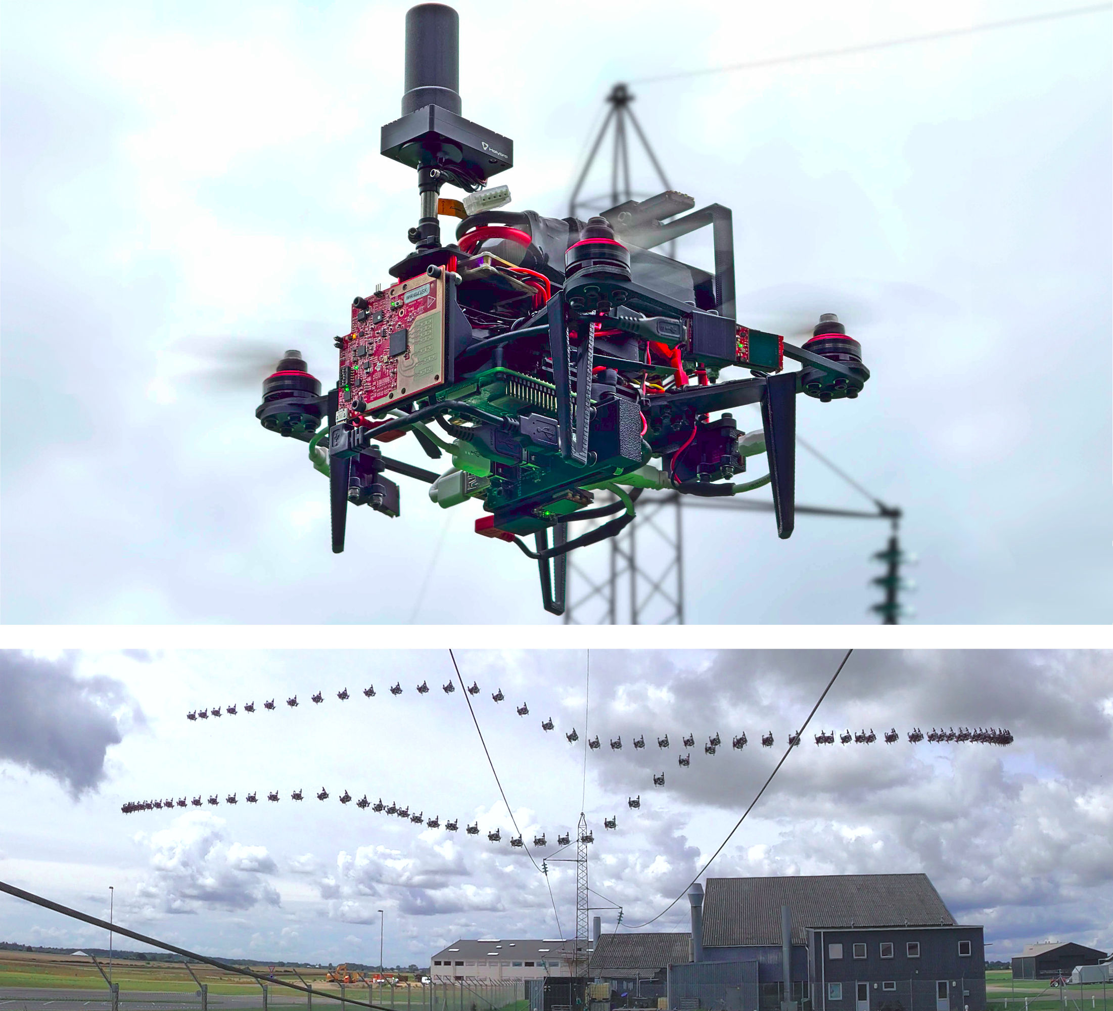
The researchers designed a system using six compact solid-state mmWave radar modules mounted around the drone's frame. Each module has its own field of view, and together they tile a complete sphere around the aircraft. This gives the drone awareness in all directions simultaneously. If a power line threat appears from any angle, at least one radar detects it.
This omnidirectional arrangement isn't incidental. Power lines can approach from any direction relative to the drone's flight path. The drone might be flying toward a line, parallel to one, or have one slip behind as it moves. Without coverage in all directions, you'd need an external observer or pre-planned knowledge of where every wire is. Omnidirectional sensing lets the drone handle unexpected encounters.
System seen from multiple angles showing radar module placement. Top image shows GPS receiver, battery, and autopilot locations. Bottom image shows USB hub, Raspberry Pi, and radar sensor positions.
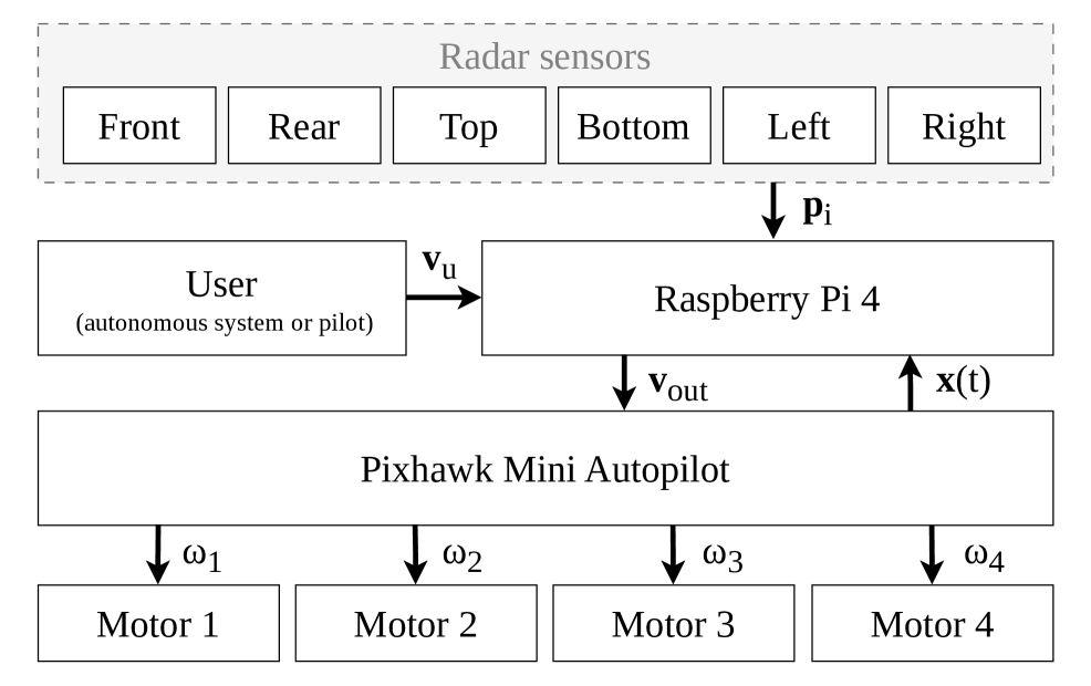
The drone's computational architecture integrates six radar sensors through a central Raspberry Pi, distributing processing across USB connections to handle real-time data fusion.
The engineering challenge is keeping the system lightweight and power-efficient. Each radar module is compact, but six of them add mass. The computational load of fusing six radar streams in real time requires dedicated processing. The researchers integrated a Raspberry Pi 4 to handle data fusion and avoidance computation while keeping total system weight manageable.
Understanding radar's quirks
Before the avoidance algorithm makes sense, it's important to understand what radar actually measures when pointed at a power line. The measurements have peculiarities that shape the algorithm's design.
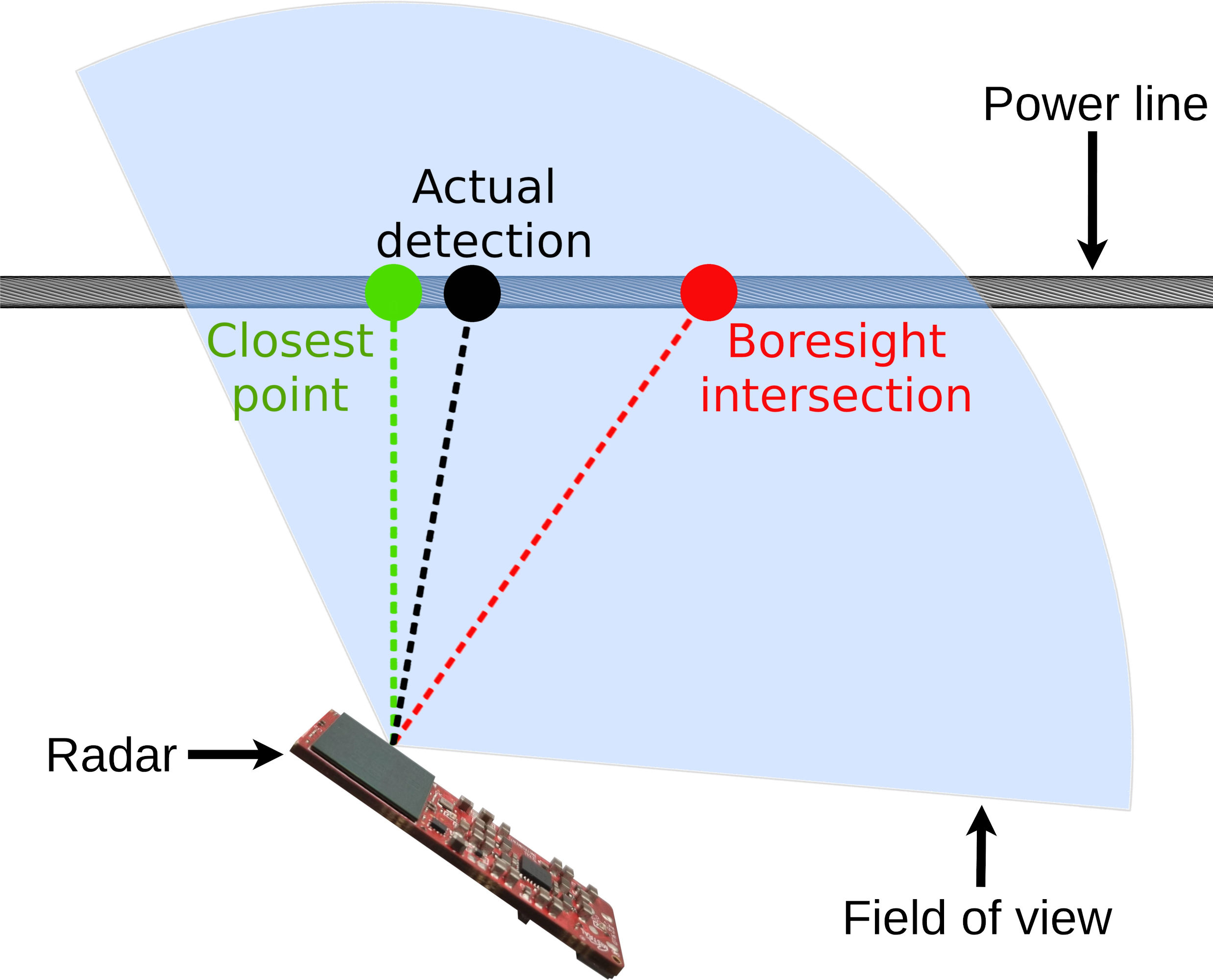
When a radar sensor points directly perpendicular to a power line, the measurement is straightforward. The echo returns from the line's direction, and the distance is clean. But power lines and drone flight paths don't align neatly. The drone often approaches at an angle.
When this happens, something counterintuitive occurs. The radar doesn't detect the closest point on the wire. It detects the point where the radar's transmit beam aligns best with the wire's orientation. If the wire runs along the direction of the radar beam, the signal reflects along the wire rather than back at the sensor. The measured direction to the power line can differ significantly from the true direction to the closest point.
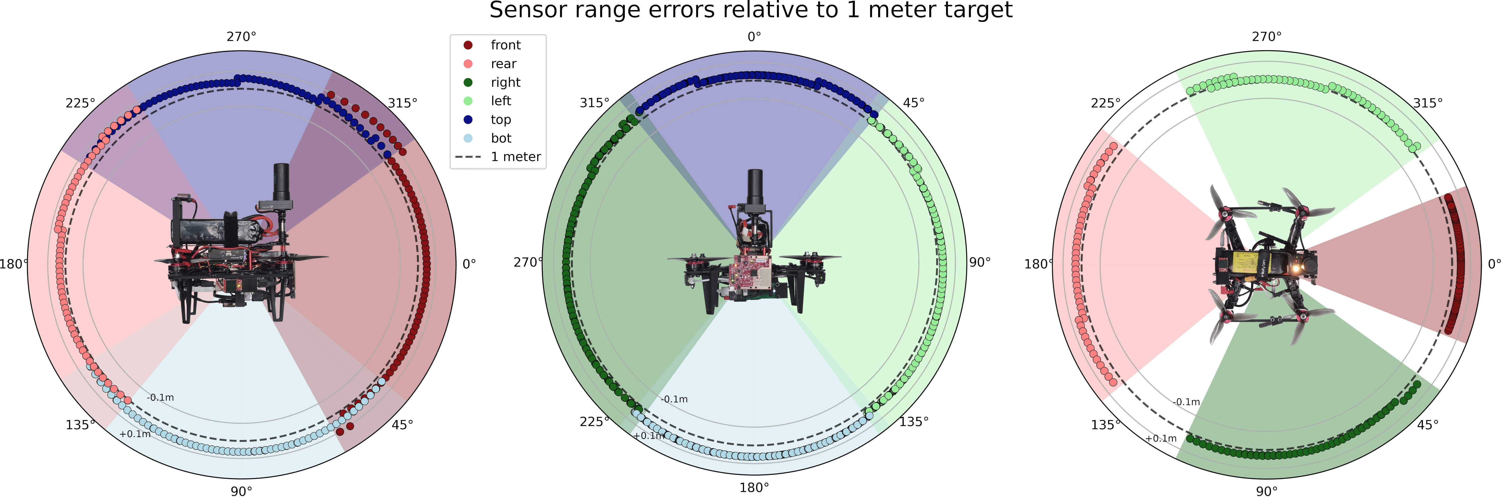
Visualization of radar sensor field of view and measurement errors at one meter distance across three perpendicular planes. Dots show individual measurements while shaded regions indicate measurement uncertainty.
Radar measurements scatter around the true target location in a predictable pattern that depends on angle and distance, informing the algorithm's tolerance for positional uncertainty.
This is crucial to understand. If you don't account for it, the avoidance algorithm seems arbitrary. Once you recognize it, you see why the algorithm must measure angles carefully and adjust its steering logic based on approach angle.
Diagram showing radar detection geometry when the sensor boresight is at an angle to the power line, with annotations highlighting where detections occur.
When radar is aimed at an angle toward a wire, the detected point differs from the closest point due to beam alignment effects.
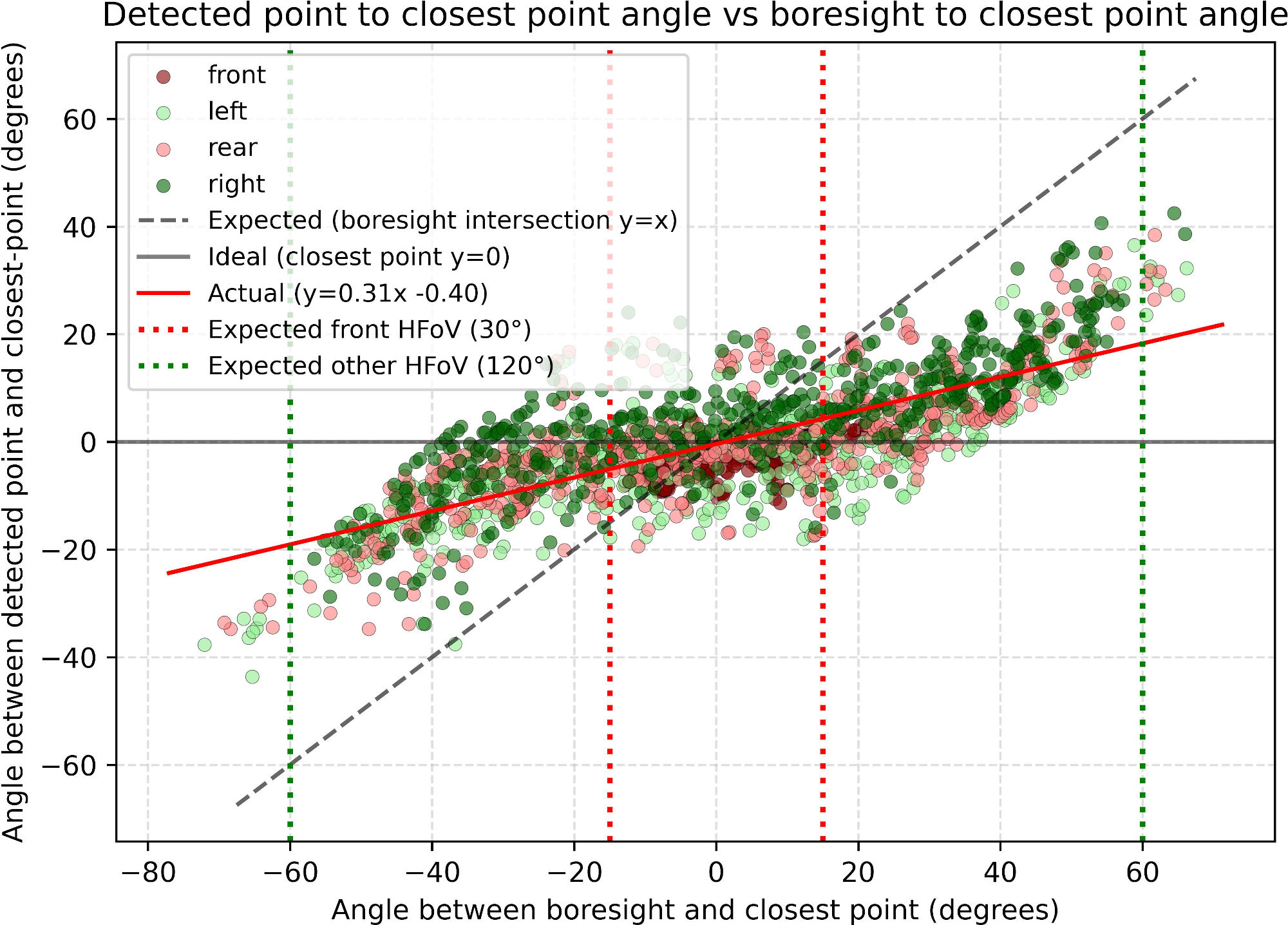
The relationship between the angle at which the drone approaches and where the radar detects the power line is non-linear. At shallow angles, the offset is small. At steeper angles, the error grows. The researchers characterized this relationship empirically and fed it directly into the avoidance algorithm.
Plot showing the relationship between detected angle and closest point angle, demonstrating the non-linear relationship as the radar boresight angle varies.
The angular detection error varies non-linearly with approach angle, a characteristic that the avoidance algorithm compensates for during real-time steering decisions.
From detection to avoidance
The avoidance algorithm translates radar measurements into steering commands. It operates differently depending on the drone's flight speed because physics imposes hard constraints.
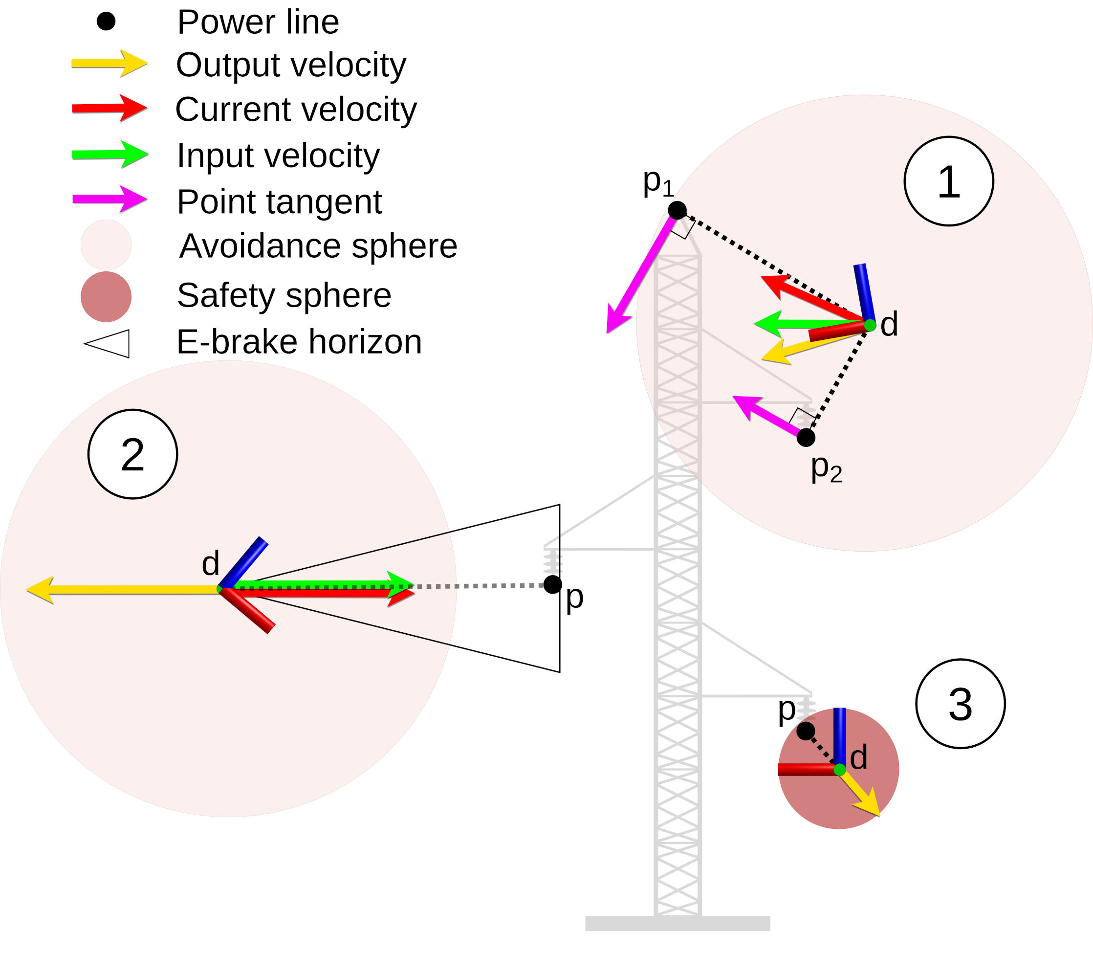
At moderate speeds, the drone has time to react to detections. The algorithm treats each radar detection as a point and computes tangent lines around the cluster of detections, effectively outlining the power line's presence. The drone then steers to follow these tangent lines, slipping sideways relative to the obstacle while maintaining forward progress.
At high speeds, momentum dominates. The drone can't turn sharply enough to dodge something it detects at the last moment. The algorithm switches to an e-brake horizon strategy. Detections within a critical distance trigger immediate deceleration. The closer the wire, the harder the brake. This buys time for the drone to turn while slowing its forward penetration into the danger zone.
The elegant part is automatic. The algorithm doesn't require the pilot or planner to specify which strategy to use. It seamlessly transitions from turning-based avoidance at lower speeds to braking-based avoidance at higher speeds. The strategy emerges from the physics of flight and radar detection range.
Three scenarios illustrating avoidance strategies: tangent-based avoidance at medium speeds, e-brake horizon at high speeds, and mixed strategies in between.
The algorithm adapts its avoidance strategy based on flight speed, automatically selecting tangent-based steering at lower speeds and deceleration-based avoidance at higher speeds.
Data flow diagram showing how detections from all six radars feed into the avoidance algorithm, which outputs corrected velocities.
Real-time pipeline: radar detections from all six sensors feed into the avoidance module, which computes corrections and outputs safe velocity commands to the autopilot.
The data fusion pipeline handles detections from all six radars simultaneously. Each sensor contributes its measurements. The algorithm identifies which detections correspond to the same power line (or separate lines). It then computes steering corrections that keep the drone safe relative to all detected obstacles. This real-time computation runs on the onboard Raspberry Pi, with latencies measured in tens of milliseconds.
Proof in the real world
Theory is elegant, but infrastructure inspection happens on actual power lines in actual weather at actual speeds. The researchers tested the system extensively in field conditions, on both decommissioned power lines and active infrastructure.
The results are reassuring across three critical dimensions: detection range, wire diameter, and flight speed.
The system reliably detected power lines up to 10 meters away. This is the critical range where avoidance is feasible. A detection at 10 meters gives the drone distance to compute and execute a steering correction. A detection at 2 meters leaves little margin for error, especially at high speed.
The system detected wires as thin as 1.2 millimeters in diameter. Power line networks include everything from thick transmission lines several centimeters across to gossamer-thin communication wires strung alongside. The ability to detect the thin wires matters most, since those are easiest to miss with vision-based systems.
The system executed successful avoidance maneuvers at flight speeds of 10 m/s and higher, corresponding to the speeds drones actually fly during inspection missions. At lower speeds, avoidance is trivial. At operational speeds, the radar and algorithm had to work in concert without margin.
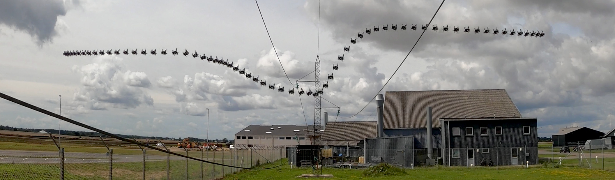
Four examples of power line avoidance in real conditions. Three examples on decommissioned power lines, one example showing avoidance of a 1.2 mm diameter wire.
Field test sequences demonstrating successful detection and avoidance of power lines ranging from thick transmission cables to thin communication wires, at operational flight speeds.
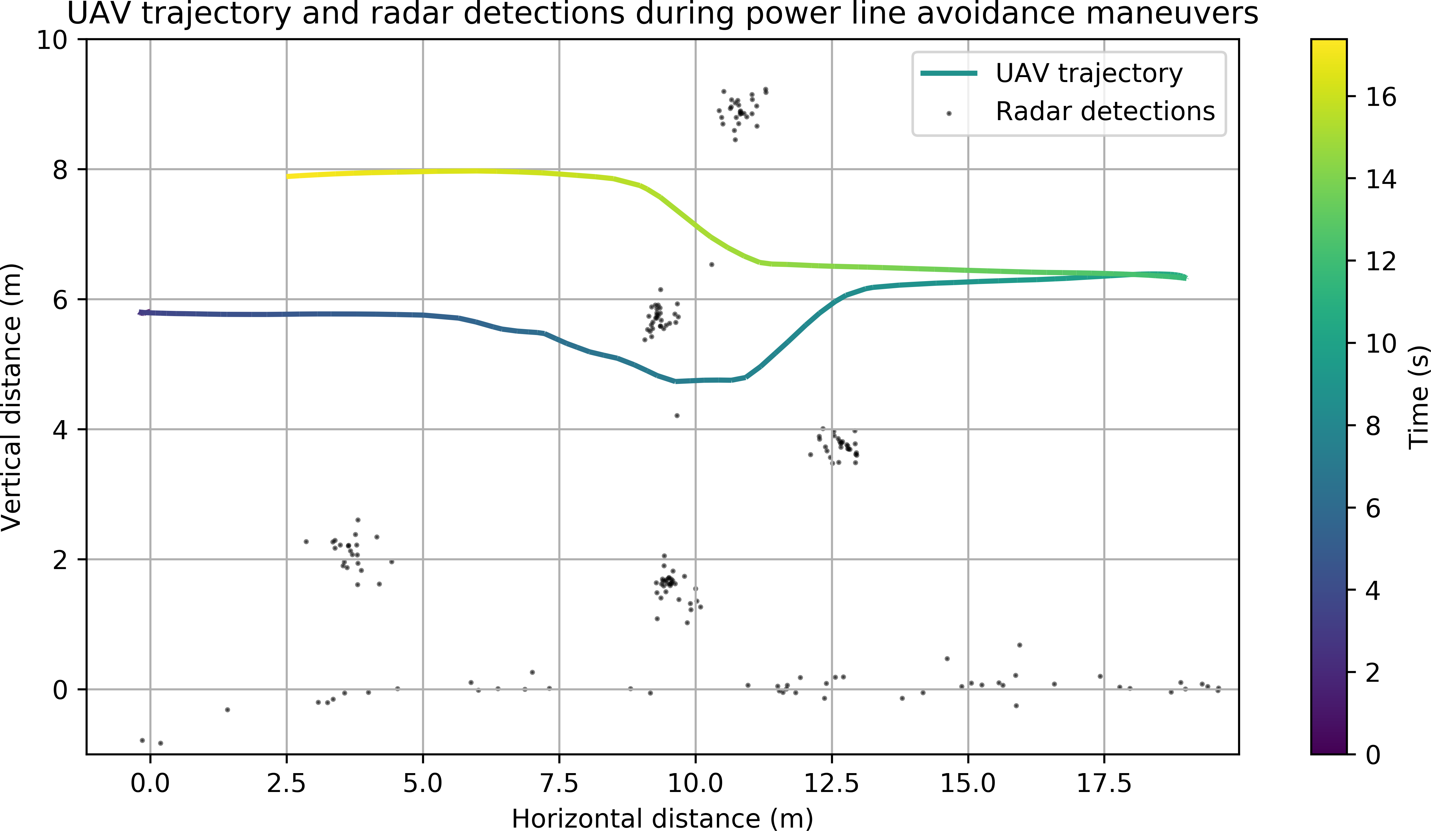
Plot of the drone's trajectory around radar detections during avoidance maneuvers, showing input velocities in the horizontal plane and corrected output velocities.
Actual flight paths during avoidance show the algorithm's steering corrections in operation, with the drone curving around detected obstacles while maintaining controlled descent.
These results demonstrate something important: the system works not just as a proof of concept, but at the operational margins where drones actually fly. It detects wires that are difficult for humans to spot from the air. It handles detection distances and speeds that real inspection missions require.
Why this matters
The genius of this system is its honest scope. It doesn't attempt to build a perfect 3D map of power line geometry. It doesn't claim to work in all conditions. It solves a narrower, more urgent problem: provide the drone with fast, directional awareness of conductive obstacles in real time, and let a simple algorithm handle the steering.
For infrastructure inspection, the use case driving autonomous drone adoption, this is exactly what's needed. A safety layer that works when cameras fail, when visibility collapses, when the mission matters most. The system operates alongside existing sensors rather than replacing them. In daylight, cameras provide rich context. In darkness or fog, radar provides essential directional guidance.
The field results show the system is ready for deployment. It reliably detects and avoids power lines under conditions where vision-based systems have failed. It operates at the speeds drone missions require. For power companies and telecommunications firms deploying autonomous inspection systems, this represents a concrete path forward: add omnidirectional mmWave radar, integrate the avoidance algorithm into the flight controller, and significantly reduce collision risk.